EARTH CONTINUITY TESTING – AN IN-DEPTH LOOK
EARTH CONTINUITY TESTING – AN IN-DEPTH LOOK
The need to perform continuity testing
For initial verification of a new electrical installation, or an addition or alteration to an existing installation, it is required that the new installation is inspected and tested to verify compliance with BS 7671 Incorporating Amendment 2:2022 Requirements for Electrical Installations (BS 7671).
The first test in the required sequence of tests is the continuity of conductors, see Regulation 643.2. This requirement is to test the continuity of protective conductors, including protective bonding conductors and ring final circuit live conductors.
Regulation 643.1 makes a requirement to use test instruments complying with the relevant part of BS EN 61557. For earth continuity testing the relevant standard is BS EN 61557-4 which requires the instrument to deliver a test voltage of 4-24V, a test current of 200mA and a resolution of 0.01Ω. The instrument may be a single function instrument or more usually a multi-function instrument.
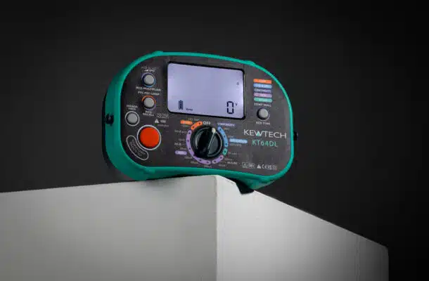
The Kewtech KT66DL is a multi-function instrument that is capable of running the full range of installation tests and fully complies with the relevant parts of BS EN 61557. The KT66DL has test current ranges of 15mA and 200mA together with an audible buzzer which sounds when the resistance is less than 2Ω. The audible continuity buzzer is a very useful aid when carrying out fault finding and circuit tracing. The Kewtech KT300DL is a small, light and compact instrument that will perform continuity testing and complies with BS EN 61557-4.
Preparing to carry out a continuity test
- Seek permission to isolate, carry out a safe isolation procedure and ensure the supply is locked off.

- Do not disconnect any protective conductors with the installation energised.
- Select the instrument to be used and inspect it to ensure it is not damaged and is in good condition. The instrument batteries should be charged and the instrument calibrated. If it has not recently calibrated check for ongoing accuracy using a test box or a known resistance.
- Select a good quality set of leads that are flexible and verify they are undamaged. Select a good quality set of probes and clips. The Kewtech ACC065 lead set are ideal for both dead and live testing as they have 4mm exposed tips that meet the requirements of the Health and Safety Executive Guidance Note GS 38 (optional fused conversion croc & probe upgrade using the ACC070 set) .
- Switch on the instrument and select the continuity testing range.
- Then join the test leads together and null out the resistance of the test leads. If using test clips join them together long side to long side (bottom to bottom jaw) to ensure the test current does not pass through the hinge and then null out the lead resistance. If using a long lead connect this in circuit and null out the lead resistance before use.
- If using clips use ones that have parallel jaws rather than ones that only come together at the tips. They should have a good “bite” from a strong spring for improved accuracy.
Performing the Test
- If performing an R1 +R2 test one end of the circuit must be disconnected. It is usual to do this at the supply end with the line and CPC conductor ends shorted together. Wago type connectors are ideal for shorting conductors together as they are easy and quick to apply, do not damage the conductors and are easy to remove. The measurement is then taken at each point of termination and at the far end of the circuit. When carrying out this test at a socket a KEWCHECK R2 socket adaptor can be used to connect the test leads to the line and earth terminals of the socket. If the socket is of poor quality, worn with weak springs or the connections are oxidised, the test may need to be performed on the socket tubes with probes at the rear of the socket in order to obtain an accurate reading.
- If carrying out an R2 test, often known as a long lead test, one end of the conductor must be disconnected from the earth terminal or bonding clamp or connected exposed conductive part. This is done to prevent parallel parts masking a break in the conductor under test.
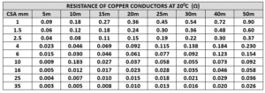
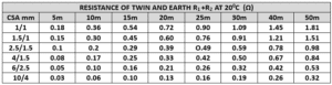
- Having carried out the test it is then necessary to compare the test result to the estimated conductor length and cross-sectional area expected resistance. The tables below provide guidance for this purpose. Lower than expected test readings indicate the presence of parallel paths. Higher than expected test results indicate possible loose or corroded connections, insulation under termination screws or, joints in the cable of reduced CSA conductors. Investigation will be required to determine the cause of the variation of the test result. Tables are provided below to help in determining expected test results.
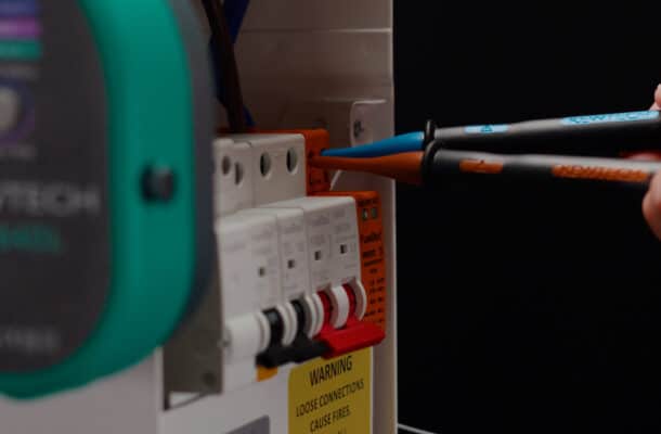
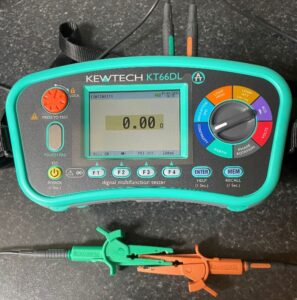 Nulling lead resistance with clips correctly connected.
Resistance Tables for comparison of test results.
Post Test
- Record the test result.
- Remove any shorting links used for the testing process.
- Re-connect any conductors that have been disconnected.
- Replace and secure any covers removed for the testing process.
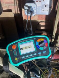
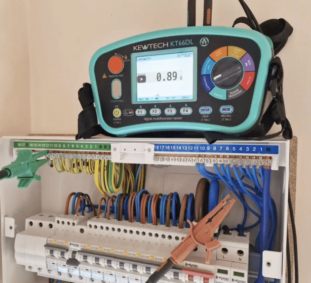
R1 + R2 Test on a workshop socket.
Periodic Inspection and Testing
Unlike initial verification the objective for Periodic Inspection and Testing is set out in Regulation 651.1 which says, “shall be carried out in accordance with 651.2 to 651.5 in order to determine, so far as reasonably practicable, whether the installation is in a satisfactory condition for continued service”.
There is a set sequence of tests for initial verification with dead tests that have to be passed to enable the installation to be energised for live testing. There are no sequence of tests or specific tests for periodic testing as the installation is already energised.
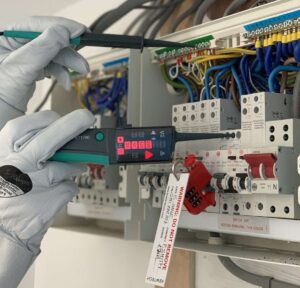
An import test to be applied is earth continuity to ensure that extraneous and exposed conductive parts are earthed. Earth continuity may be verified by earth loop testing. Where earth continuity needs to be verified, and for safety avoiding exposing live parts, or dismantling equipment, earth continuity may be proved by probing parts with a test probe connected to a continuity tester. One terminal of the instrument should be connected to a known earth source and the other to a test probe. For example, trunking, conduit, light fittings and electrical equipment in a plant room may be rapidly tested using a long lead and a continuity tester connected to a known earth source.
A convenient earth source for carrying out the test may be a local socket outlet. First carry out an earth loop impedance test on the socket to prove that it is earthed. Then using a KEWCHECK R2 socket adaptor plugged in to the socket, a long lead plugged in to the earth terminal of the adaptor and connected to the continuity tester. The Kewtech ACC50MTL is a 50m flexible test lead wound on to a drum and is ideal for earth continuity testing and earth bond testing. With this test set up rapid testing for continuity can be safely performed by sample testing of exposed conductive parts in an area by probing them and reading the result. The person performing the test will need to use engineering judgement as to the test result being appropriate for the circuit under test. It is recommended that all Class 1 wall light fittings are tested for earth continuity, rather than sampled, as they are commonly found to be unearthed. To avoid working at heights, high level light fittings can be probed using and a fibre glass insulated telescopic pole fitted with a test probe.
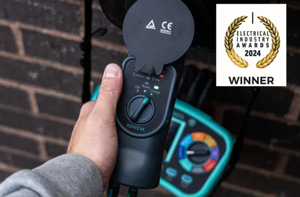
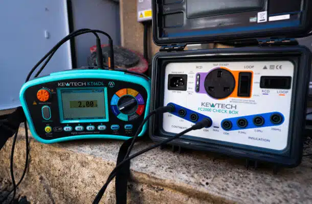
Set up ready to carry out a periodic continuity test.
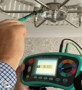
Verifying earth continuity on a Class 1 light fitting
More News Articles
16 Apr 2025
Why and how to test SPD’s?
2 Dec 2024
INSPECTION & TESTING SAFETY EXPLAINED