Installation of EV Charging Points
THE INSTALLATION OF ELECTRIC VEHICLE CHARGING POINTS!
There is already a demand for the installation of Electric Vehicle (EV) charging points in both domestic and commercial premises. The Government have declared that the sale of petrol and diesel fueled road vehicles will be banned after 2030 and a further ban on the sale of hybrid vehicles in 2035. The Government have indicated that it will be a requirement for the building of new homes to have an EV charging point installed at the time of construction. It is clearly evident that the demand for the installation of EV charging points will increase from the current level.
The installation of EV charging points, just like any other LV installation, requires compliance with BS 7671 2018 The Wiring Regulations. In addition, an EV charging installation is one of the Special Installations or Locations listed in Part 7 of BS 7671. An updated Section 722 for Electric Vehicle Charging Installations was issued as Amendment 1 to BS 7671 in 2020.
If a contractor is asked by a client to install an EV charging point the first step for him is to verify what the exact requirements of the client are, and to carry out a site survey. The client’s requirements will pivot around the location of the EV charging point, the vehicle type and battery capacity and how fast they want the vehicle to charge. For most single-phase domestic installations this will be a 3 kW to 7.2 kW EV charger. For commercial installations an additional requirement will be how many vehicles they want to charge simultaneously and how quickly. In both settings Load Curtailment can be utilised to prevent the overloading of the available supply.
KEY FACTORS TO BE VERIFIED…
The key factors to be verified by the contractor during the site survey will be the supply capacity, the number of phases, the earthing system, the existing maximum demand on the installation and the available spare capacity, the spare ways on the distribution board or consumer unit, the Zs at the DB or consumer unit and the desired location of the EV charging point. The contractor should verify if the premises are on a looped supply cable from an adjacent premises. DNOs will not permit the use of a looped supply for EV charging and an additional DNO supply cable will be required. The contractor can then verify the length of cable run, the type of cable and the cable installation method. Each EV charging point has to be connected to its own individual circuit protective device in accordance with BS 7671 Regulation 722.533.101.
If the maximum demand on the supply, including the proposed EV charging, does not exceed 60A the installation can go ahead but must be notified to the Energy Networks Association (ENA) via their web site. If the maximum demand will exceed 60A then the District Network Operator (DNO) will need to approve the installation before the installation commences.
EV charging are high current long hour loads. The contractor will need to seek information from the manufacturer to verify the circuit protective device and the type of consumer unit, or distribution board, requires additional considerations for these long hour loads. This may involve uprating an MCB by one size, and consequentially the cable cross-sectional area, and spacing of the MCBs. Connecting EV circuits to plastic consumer units is not recommended. It may be more appropriate to split the tails to a consumer unit, install a service connector and a switch fuse to supply the EV circuit. Having gathered all the required information from the site survey the contractor should then, just like
any other installation, carry out a design for the new circuit to comply with BS 7671.
If the EV charging point is going to charge the vehicle outside, and the installation has a PME earthing system, then Section 722 requires one of 5 the listed provisions for shock protection set out in Regulation 722.55.101.0.201.1. Where the DNO has supplied an earth to the premises from an incoming cable, regardless of the appearance of the connection to the cable, it is highly likely to be a TN-C-S (PME) due to repairs to the cables in the street using a Combined Neutral and Earth (CNE) cable. Alternatively, the EV point can be isolated from a PME supply earth using an isolating transformer complying with Regulation 722.413.1.2.
These additional measures are intended to protect persons against shock, if the PME PEN conductor becomes open circuit the vehicle body may become live even if the supply is disconnected or any circuit protection trips. A person touching the body of the vehicle, whilst in contact with the ground or an exposed or extraneous conductive part, could receive a fatal shock.
Alternatively, the EV charging point could utilise a TT earthing system by connecting it to an earth electrode and not the supply earth. The EV charging Point RCD then will provide Fault and Additional Protection. However, the earth electrode will need to have a separation distance between any underground metallic pipe work connected to the supply earth via main protective bonding. This is to prevent a transfer of potential from the PME earth and the TT electrode, DNOs will have minimum separation distances usually greater than 3m.
EV CHARGING POINTS ARE REQUIRED TO HAVE 30mA RCD PROTECTION.
EV charging points are required to have 30 mA RCD protection. This can be installed to protect the EV charging point supply cable or more usually in the EV charging point itself. The RCD must comply with BS EN 61008-1, BS EN 61009-1, BS EN 60947-2 or BS EN 62423 in accordance with BS 7671 Regulation 722.531.3.1. To prevent the RCD from being rendered inoperable by any stray DC currents the RCD as a minimum has to be a Type A with additional RDC-DD protection. Type B RCD protection can be used without RDC-DD protection. Full compliance with one of the listed RCD BS ENs has to be achieved.
Some EV charging products do not have individual RCDs inside but rely on electronic protection on a printed circuit board these, are not compliant with the full range of requirements of the RCD standards and should not be used. Look for the presence of a user RCD test button as this is one of the RCD standards requirements. For any EV charging point ask for a Declaration of Conformity (DoC) from the manufacturer listing all the BS or BS EN requirements set out in Section 722. The charging equipment, or the packaging, should have a CE, or UKCA or UKNI marking. Manufactures of quality equipment will only be too pleased to provide their DoC and may even list it on their web site.
Just like any other installation BS 7671 requires the EV circuit to be inspected and tested “during construction and on completion before being put in to service”. EV charging points will need to have a loop impedance test and an RCD test. As these EV units will be mostly installed outside there is an added risk of shock to the inspector as this involves live testing.
The Electricity at Work Regulations (EAWR)1989 Regulation 14 forbids working on or near live parts unless it is necessary in all the circumstances, so should be avoided if a test can be done some other way?
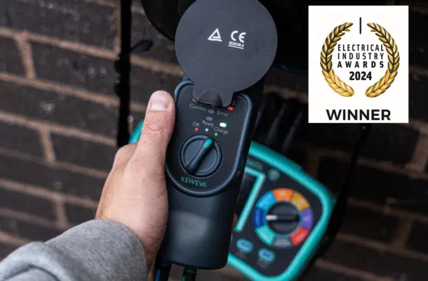
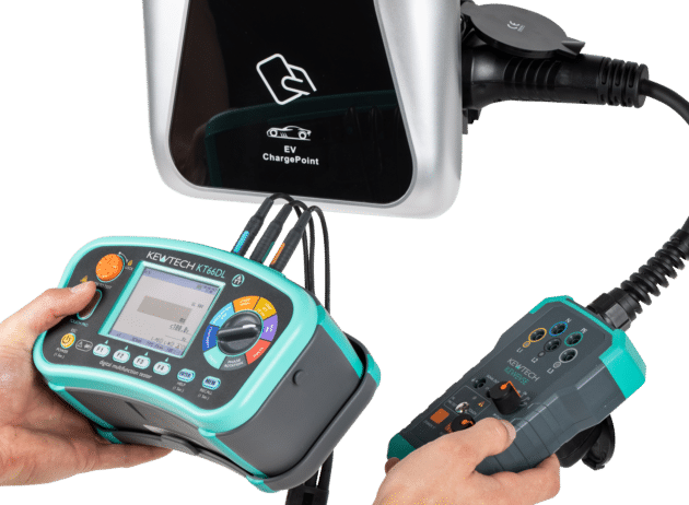
The loop test and RCD can be carried out with a Multi-Function instrument using probes, maybe with the inspector standing on a rubber mat to minimise the shock risk. To minimise the risk further and to avoid live testing of exposed terminals in compliance with the EAWR, an EV adaptor lead should be used. This plugs in to the EV charging socket to simulate the presence of an electric vehicle and to complete earth pilot connection to energise the socket. With the adaptor plugged in to a MultiFunction Tester the required tests can be carried out quickly, conveniently and with considerably less shock risk.
KEWTECH’S COMPREHENSIVE EV TESTING EQUIPMENT…
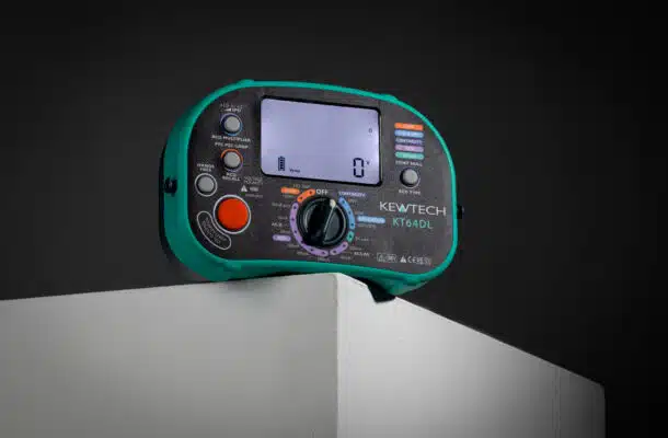
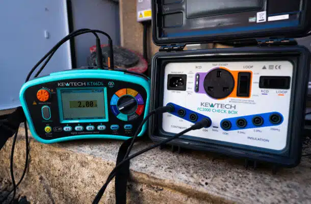
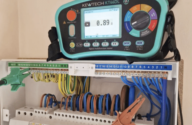
The new Kewtech KT66DL carries out a full, and extended range, of installation tests required by BS 7671. The KT66DL paired with Kewtech KEWESVE adaptor lead facilitates EV charging point tests required by BS 7671, for both Initial Verification and Periodic Testing, speedily and safely. The KT66DL has a range of additional EV tests for verifying the functionality of different types RCD. These additional RCD test facilities are really helpful for both fault finding and confidence testing.
